
Do not perform the following instructions without approval from a Pollen Sense Technician, doing so may cause irreversible damage to your sensor. Please review the instructions in their entirety before attempting to operate on the sensor.
In order to properly perform the Tape Drive Replacement, you should relocate the sensor to a clean, indoor location where you are free to take it apart and will not lose parts/screws. Do not have the power connected while operating on the sensor. Various hand tools including torx & hex bit screwdrivers, tweezers, and snips are required to complete the following instructions.
Contents:
Nomenclature

The Controller Board may look slightly different depending on the model of your APS-400 Sensor. This will not cause any issues in the following instructions.
Hardware Differentiation
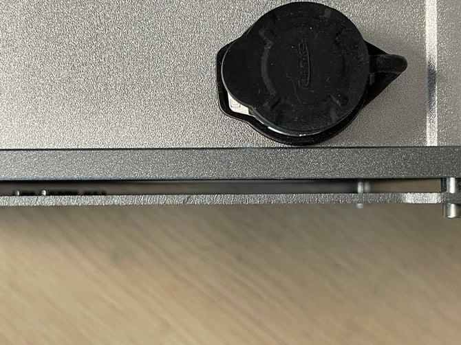
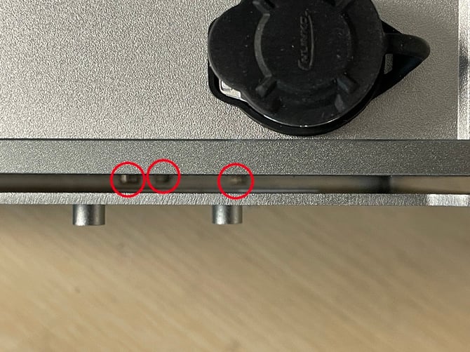
There has recently been an update to the hardware of the APS-400 sensor, resulting in two sets of instructions to replace the tape drive assembly. The best way to correctly identify the hardware in your APS-400 sensor is to view the space between the attachment plate and base plate, underneath the power connector (view images below for reference). The new hardware requires 3 screws to be attached to the Tape Drive Assembly from the outside of the sensor for easier access. Adhere to the set of instructions that matches your sensor’s hardware based on the information below. If you require assistance to correctly identify the hardware of you sensor, reach out to a Pollen Sense Support member.
Base Plate Original |
Base Plate Removable Drive |
| No screws attached to the Tape Drive Assembly outside of the sensor. Please follow the Base Plate Original instructions. | 3 screws attached to the Tape Drive Assembly outside of the sensor. Please follow the Base Plate Removable Drive instructions. |
 |
 |
Base Plate Original
-
Open the lid of the sensor and remove the media cartridge.
-
Close the lid and turn the sensor over to reveal 4 screws holding the base plate and enclosure together. Carefully remove these 4 screws, keeping the lid face down.

-
Holding the sensor together, turn it back over so the lid is facing up.
-
Open the lid and remove the fan from its mount. Do this by pushing the top rubber pin away from the fan exhaust, then pulling out the right rubber pin.

- Using snips, cut and remove the zip tie holding the fan cable to the lid. Be very careful to ensure you do not accidentally cut the fan cable.

-
Place the fan between the Microscope Assembly and Tape Drive Assembly to keep it out of the way for the following steps.
-
Remove the ethernet cable from the Controller Board. You may have to shift the enclosure around a bit in order to give it enough room to be removed.

- Slowly lift the enclosure straight up from the base plate and lean it on its side to the left of the base plate. There are still some wires connected to the enclosure, be sure not to damage them when removing.

- Remove the power cable from the Controller board.

- Remove the antenna cable from the Controller Board.

-
Set aside the lid and enclosure away from the base plate to give yourself more room to continue operating.
-
Remove the Raspberry Pi from the Controller Board. Be very gentle when doing this, the parts holding this together are extremely fragile. It is helpful to use tweezers to pry the Raspberry Pi from behind.

-
Turn the base plate to view the back side of the Microscope Assembly. Take note of how the white cable is installed into the rear of the Microscope Assembly. The two possible orientations are shown below. If this cable is reinstalled improperly in a later step, the sensor will undergo irreversible damage when powered back on.
- Remove the white cable from the Microscope Assembly by first flipping open the black clip, then pulling the cable straight out of the connector.

-
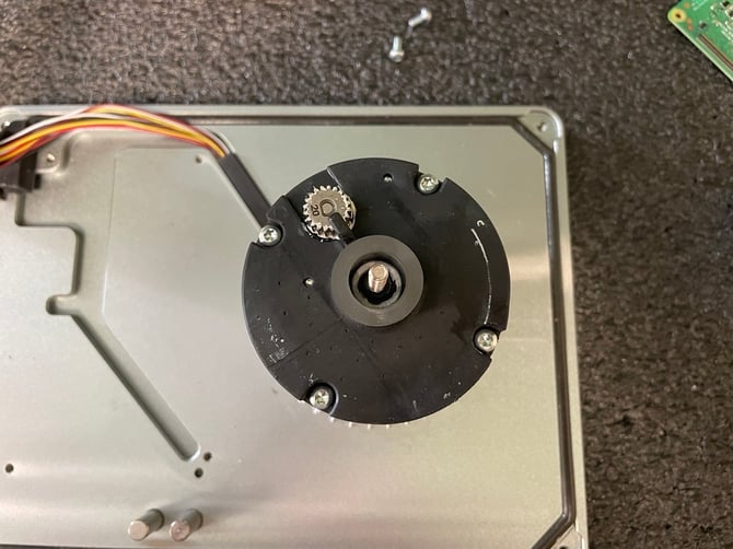
Turn the base plate to now view the front of the Microscope Assembly. Remove the screw in the mount holding the Controller Board in place.
-
Remove the board mount.

- Remove the Controller Board from the board mount towards the rear of the Microscope Assembly. Do so by gently prying the pin of the board mount out of the Controller Board and lifting it up and to the right of the mount. This part is very fragile and can easily break, be extremely careful when performing this operation.

-
Set the Controller Board to the left of the base plate.
-
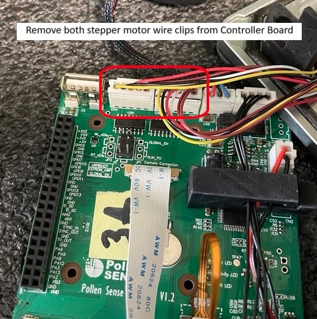
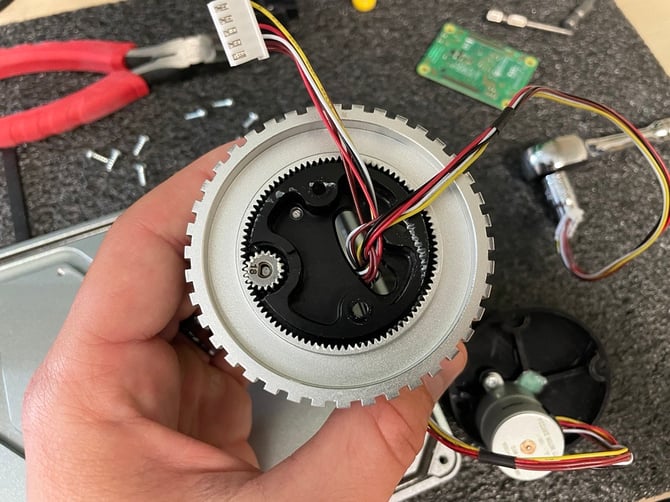
Remove the 2 stepper motor wires from the Controller Board. These connectors each have 5 pins on them, they are the largest of all the connectors on the Controller Board.
-
Important: Your sensor may have had only a single stepper motor installed, this is a more previous hardware configuration. Remove this stepper motor as described and continue with the instructions.
-
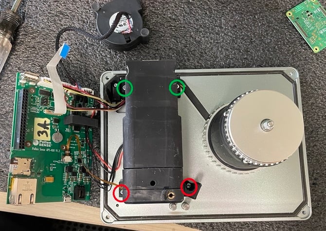
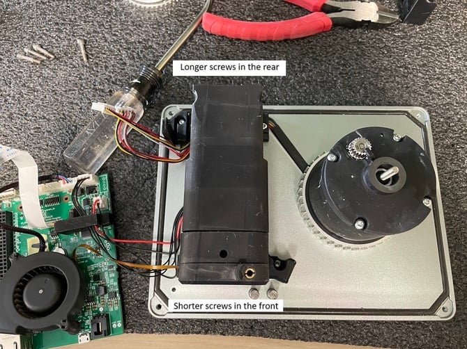
- Remove the 4 screws holding the Microscope Assembly to the base plate. Note that the 2 screws in the rear (circled in green) are longer than the 2 screws in the front (circled in red).
-
With the stepper motor wires removed, lift both the Controller Board and Microscope Assembly away from the base plate and set them aside.
-
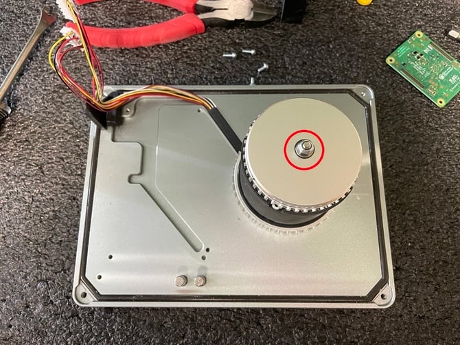
Remove the locknut, silver washer, and black washer from the Tape Drive Assembly.1
-
Remove the uptake gear (silver gear from the top of the Tape Drive Assembly) and set aside. You will reinstall the uptake gear with the new Tape Drive Assembly.
-
Important: a small spring may have been installed underneath the uptake gear, around the bolt of the Motor Drive Assembly top. Please remove and discard this spring, you will not be reinstalling it.
-
-
Remove the 4 screws from the top of the Tape Drive Assembly. Lift the top up and set aside, you will not be able to pull the stepper motor wires all the way out yet.
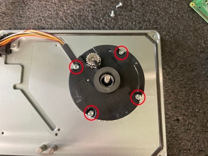
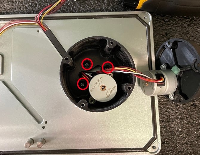
- Remove the 3 screws holding the Tape Drive Assembly to the base plate.
-
Lift the Tape Drive Assembly away from the base plate. Remove the feed gear (remaining silver gear attached to the assembly) and set aside. You will reinstall the feed gear with the new Tape Drive Assembly.
-
Important: a small spring and friction brake (small, black plastic piece) may have been installed inside of the feed gear. Remove and discard this spring and friction brake, they will not be reinstalled with the new Tape Drive Assembly.
-
-
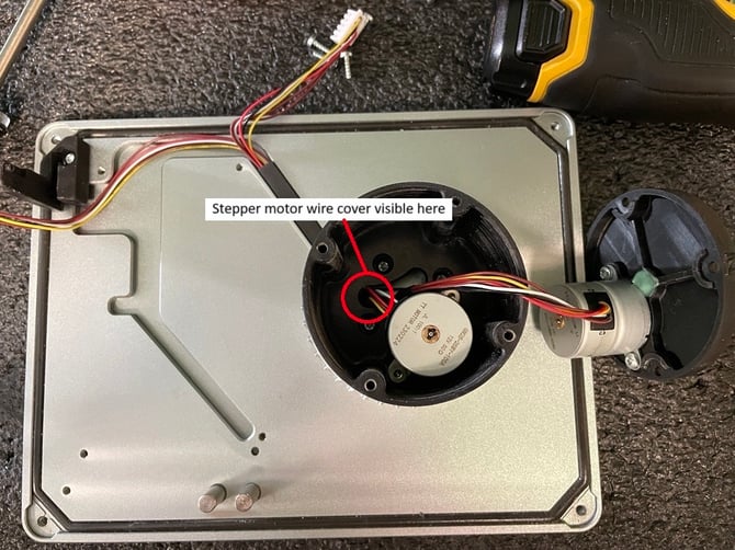
Remove the stepper motor wire cover in the slot of the base plate leading from the Tape Drive Assembly towards the Microscope Assembly. You will reinstall this piece in a later step.
-
You will no longer need any of the black pieces of the Tape Drive Assembly or the stepper motors attached to them. The new Tape Drive Assembly comes with these parts preinstalled.
-
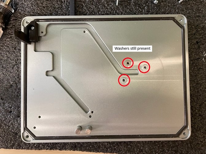
There should be 3 washers left on the base plate where the Tape Drive Assembly once was. Do not remove these washers, they provide proper clearance for the feed gear to move smoothly.
-
Using a dry paper towel, clean the base plate of any visible debris.
-
Remove the 4 screws holding the top of new Tape Drive Assembly.
-
Place the feed gear (refer to step 25) onto the bottom of the Tape Drive Assembly. The black ring inside of the feed gear will face towards the Tape Drive Assembly. Feed the wires of both stepper motors through the feed gear when installing.
-
Attach the Tape Drive Assembly to the base plate using the 3 screws removed in step 24. Do not yet fully tighten these screws as it is possible to crush the stepper motor wires.
-
Place the stepper motor wires into the diagonal slot in the baseplate leading from the Tape Drive Assembly towards the rear of the Microscope Assembly.
-
Replace the stepper motor wire cover into the slot and slide underneath the Tape Drive Assembly until visible in the location specified below. This keeps the stepper motor wires in a safe location while fully tightening the Tape Drive Assembly to the base plate.
-
Fully tighten the 3 screws attaching the Tape Drive Assembly to the base plate.
-
Replace the Tape Drive Assembly top and attach using the 4 screws removed in step 30.
-
Pull the wires of both stepper motors out from the Tape Drive Assembly as far you can without damaging them. You will need all possible slack in order to connect them to the Controller Board in a later step.
-
Place the uptake gear (refer to step 22) onto the top of the Tape Drive Assembly.
-
Place the black washer first, then silver washer, then locknut onto the bolt of the Tape Drive Assembly. These were removed in step 21.
-
Tighten the locknut until snug, then loosen 1/4 turn. There should be some slight play in the uptake gear when properly tightened (the uptake gear will only move a degree or so in each direction, but it should not require much force to wiggle it).
-
Attach the Microscope Assembly to the base plate using the 4 screws removed in step 18. Note again that the longer screws are used to attach the rear of the microscope and the shorter ones to attach the front.
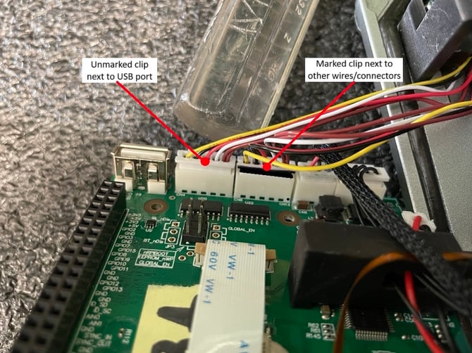
- Connect the stepper motor wires to the Controller board. The orientation of these wires is critical to the operation of the sensor. The clip at the end of one of the stepper motors has a black mark on it. View the image below for the correct orientation.
-
Reinstall the Controller Board into the rear board mount. The pin on the mount must sit in its designated hole on the Controller Board in order to be mounted correctly. Ensure that none of the wires between the Controller Board and Microscope Assembly are being crushed.
-
Reinstall the front board mount removed in step 15.

-
Reinstall the Raspberry Pi onto the Controller Board.
-
Replace the thermal foam pad onto the CPU of the Raspberry Pi. This foam pad may have been stuck to the side of the enclosure. If it is no longer present, it must be replaced with another thermal foam pad or thermal paste.

-
Reconnect the white cable to the rear of the Microscope Assembly in the same orientation as noted by you in step 13. Be sure to first open the black clip, slide the cable in, then close the black clip. The pins of the cable need to sit evenly inside the connector on the Microscope Assembly.
-
Ensure both micro SD cards are fully installed in the Controller Board, you may need to press them back in.

-
Set the sensor’s Enclosure on its side and to the left of the Base Plate
- Attach the power cable to the Controller Board.
- Attach the antenna cable to the Raspberry Pi.
- Lift the Enclosure and gently place it onto the Base Plate. Ensure that all components are within it and that none of the wires are pinched by the walls. View the image below for proper power cable and antenna cable management.
- Reconnect the ethernet cable to the Controller Board.
- Zip tie the fan cable to the small clip next to the fan’s mount. Cut away the excess zip tie.

-
Reinstall the fan into its mount by first inserting the right rubber pin, then rotating the fan until the top rubber pin is in place (step 4 in reverse).
-
Ensure the nozzle of the fan is properly seated in the rubber seal of the fan exhaust.

-
Close the lid of the sensor and carefully turn it over, keeping all the components together.
-
Reinstall the 4 screws removed in step 2. Do so in a crisscross pattern to allow even pressure around the seal of the enclosure.
-
Replace the media cartridge.
It is critical that you inform a Pollen Sense Technician that you have completed the reinstall. Once they receive this confirmation from you, you will be sent additional instructions on how to assist in the recalibration process. Recalibrating the sensor is absolutely essential to its function. Failure to do this will likely result in inaccurate data collection.
Base Plate Removable Drive
Instructions for this have not yet been completed since only a few sensors of this type have been deployed. If you believe you have this type of base plate, please reach out to a Pollen Sense Technician.